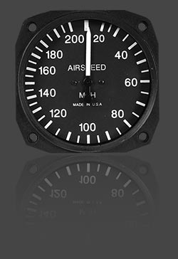
Airspeed Indicators
The Airspeed Indicator in next ASI, is a sensitivedifferential pressure gauge operated by pressures picked up by a pressure head, in the picture " P " word , which is mounted in a suitable position on theairframe. The simplest pressure head consists of an open ended tube, the pitot tube, aligned with the direction of flight, and asecond tube, the static tube, in the pcture " S " word, which is closed and streamlined at the forward end but which has a series of small holes drilledradially along its length. When moved through the air, the pitot tube will pick up pitot pressure made up of static pressure and dynamic pressure.
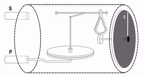
The pitot pressure is led through a pipe-line to one side of a sealed chamber, divided by a thin flexible diaphragm. The static tube isunaffected by dynamic pressure as its end is closed, however, the small holes will pick up local static pressure. The static pressure is led through a second pipe-line to the other side of the diaphragm. However, the static pressure component of the pitot pressure is balanced by the static pressure on the other side of the diaphragm so that any diaphragm movement is determined solely by thedynamic, or pitot excess, pressure. Movement of the diaphragm is transmitted through a mechanical linkage to a pointer on theface of the ASI where the pitot excess pressure (pt– p) is indicated in terms of speed.
In some installations the pitot tube and the static tube are combined into a single pressure head with the pitot tube builtinside the static tube. A heater is placed between the pitot and static tubes to prevent ice forming and causing a blockage. Drainholes in the head allow moisture to escape and various traps may be used to prevent dirt and water from affecting the instrument .
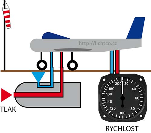
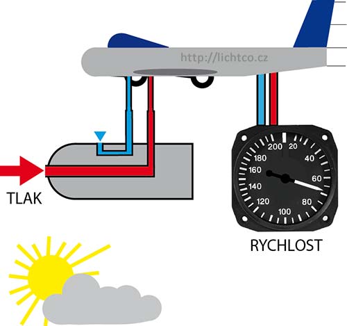
Pressure conditions in the distribution of static and dynamic / total pressure, we can imagine well-illustrated by images shown below
... 1). The first picture is the airplane on the ground, at rest or without motion. Unlike the red / blue and the total pressure, static pressure is zero and therefore speedometer shows speed value "0".
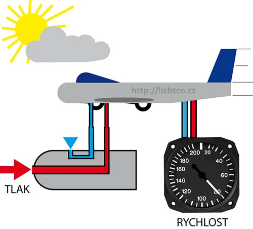
2). The second picture is now slightly more complicated situation. Flying machine (here, for clarity, aircraft) is moving forward at that pressure in the enlarged representation corresponds to the red arrow. Since the airplane is not in the zero level, changed the static pressure ratio in the branch are shown in smaller blue arrow (in fact the pressure is smaller, because we know that with increasing altitude the air pressure decreases - is declining). The difference corresponds to the speed of these pressures, which shows us the speedometer, the value "80".
3). Last change occurs when the aircraft flies at a height greater than in Fig.2, but the same forward speed. The total pressure does not change us, but drop us a static air pressure, there again shows a smaller blue arrow. What happens to the pointer speed? The speed at which the speedometer shows will be reduced compared to Figure # 2 The plane is flying at altitude lower forward speed to the outside air. This rate is also called instrumentation.
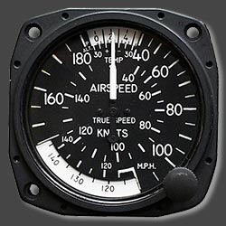
For this feature airspeedmeters are used for aircraft flying at hi altitude, instruments have an another membrane. But this is altitude membran, that regulates the leverage ratios in the gear mechanism of the device. We handle it shows the speed error corrected for height, the true air speed / actual speed. For example, in military fighter aircraft used speedometers that have two pointers. One shows the speed without correction, the second speed is corrected with altitude.
We have many types of airspeed. Some types you can see in the next :
Indicated Airspeed (IAS)
IAS is shown on the dial of the instrument, uncorrected for instrument or system errors.
Calibrated Airspeed (CAS)
CAS is the speed at which the aircraft is moving through the air, which is found by correcting IAS for instrument and position errors. The POH/AFM has a chart or graph to correct IAS for these errors and provide the correct CAS for the various flap and landing gear configurations.
Equivalent Airspeed (EAS)
EAS is CAS corrected for compression of the air inside the pitot tube. EAS is the same as CAS in standard atmosphere at sea level. As the airspeed and pressure altitude increase, the becomes higher than it should be, and a correction for compression must be subtracted from the CAS.
True Airspeed (TAS)
TAS is CAS corrected for nonstandard pressure and temperature. TAS and CAS are the same in standard atmosphere at sea level. Under nonstandard conditions, TAS is found by applying a correction for pressure altitude and temperature to the CAS.Some aircraft are equipped with true ASIs that have a temperature-compensated aneroid bellows inside the instrument case. This bellows modifies the movement of the rocking shaft inside the instrument case so the pointer shows the actual TAS. The TAS indicator provides both true and IAS. These instruments have the conventional airspeed mechanism, with an added subdial visible through cutouts in the regular dial. A knob on the instrument allows the pilot to rotate the subdial and align an indication of the outside air temperature with the pressure altitude being flown. This alignment causes the instrument pointer to indicate the TAS on the subdial.
On the following picture you can see colorized lines, so-called " RANGE MARKINGS " :
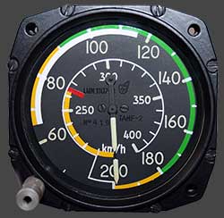 Green Arc : Normal Operating Range
The green arc shows the normal operating range of the airplane. The speed at the bottom of the green arc, abbreviated Vs1, is the stall speed with the flaps and landing gear retracted, power at idle, and the airplane at maximum gross weight. The top of the green arc shows the high end of the normal operating range, the maximum structural cruising speed, abbreviated Vno.
Yellow Arc : Caution Range
The yellow arc represents the caution range—speeds appropriate only in smooth air. The top of the yellow arc coincides with Vne, the never-exceed speed of the airplane.
Red Line : Never-Exceed Speed
A red line near the top of the airspeed range marks Vne. Exceeding this speed even in smooth air could damage the airplane structure.
White Arc: Flap Operating Range
The white arc shows the range of speeds in which it's safe to extend full flaps. The upper limit of the white arc is called Vfe, maximum flap extended speed. Extending the flaps at higher speeds could cause structural damage. The lower limit of the white arc, abbreviated Vso, is the stalling speed or minimum steady flight speed at maximum gross weight with the flaps and landing gear in the landing position...
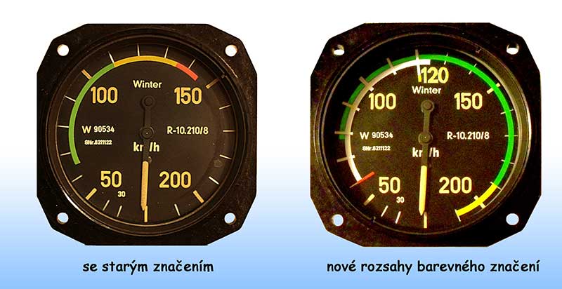
Some types of range marking :
On the picture below you can see two types of range markings. Left one is "old" type. On the right I made a new remarking in the same airspeed indicator but for a new, faster airplane.
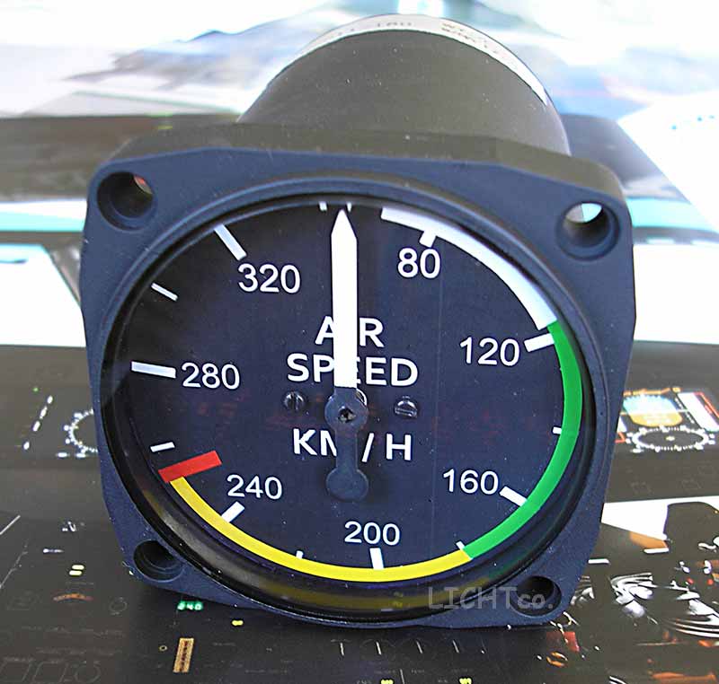
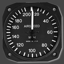
Next picture show you a different type of airspeed indicator with bigger value of airspeed.
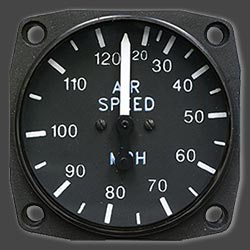
Some type of instruments face look :
I made new "range markings" for Airspeed Indicator LUN this week and I want to show you new look.
 Indicator without markings
 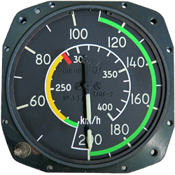 And the same Indicator with new one...