Domestic production of printed circuit boards
back to the main.. back to the simulator
2011/09/04 - FIRST PRODUCTION PCB ... Photographic method :
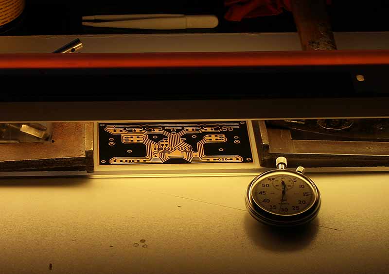
This image has next, next attempt to manufacture printed circuit boards Photographic method (as the first but led to successful goal). In previous experiments, I used a UV lamp, I tested a five-minute increments, but the results were always pitiful. On the advice of my friend when I attempt to use the normal exposure of an ordinary fluorescent lamp which is mounted such as the kitchen. I cradled her height is about 100 mm above the PCB, which was covered by a mask, printed on transparent film. (Printer LASER - MINOLTA slowest printing, foil "prehistory" FOLEX brand but it has proved.)
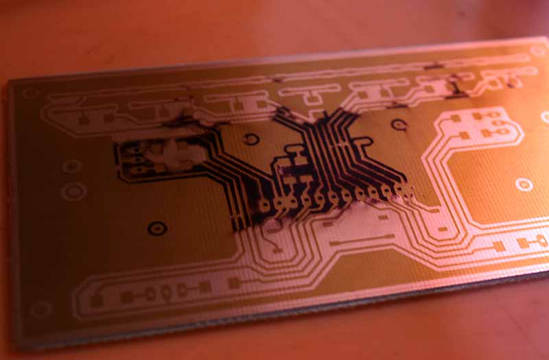
The DPS totmo picture inserted after exposure to 30-minute bath with NaOH 1.5% (Note that it is a corrosive and good to work with gloves and goggles on the eyes). The solution is washed away enlightened areas of the board and remain areas that were covered before exposing mask. After washing away the plate is washed with lukewarm water.
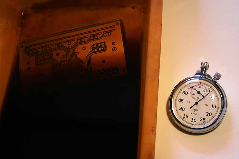
The third picture is easy to see DPS, inserted into the etching solution of ferric chloride. This board of odleptají unnecessary space and will remain only conductive connections. After the plate is washed again with water. ATTENTION ... Chloride contaminates everything nicely what droped it ! It is good to work with gloves and with extreme caution !!
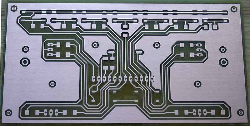
This is how the finished, washed and coated with PCB cover varnish. ( This prevents oxidation of copper ).
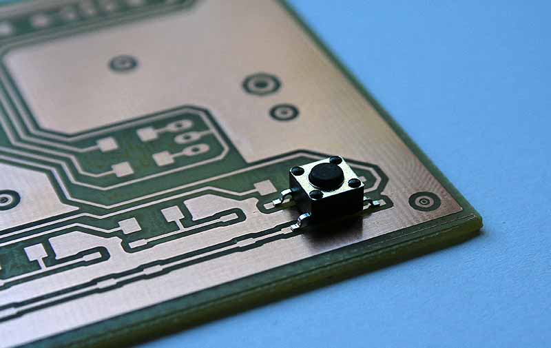
Test of the accuracy of manufactured PCB ... here only to illustrate the SMD switch attached to the surfaces, which comes after the solder.
2011/09/24 EXPERIMENTAL ESTIMATION FOR PLATE PCB exposure time:
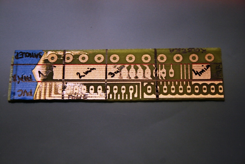
In the production of another two-sided printed circuit boards, problem occured with the lack of exposure and uneven coper went gone. Therefore, I said good-bye to the lamp and took lights way sunbathing. I use is "sun mountain". Exposure time is shortened from the original 30 minutes to 5, which is quite working time savings.
The first line of the sample was used as a mask glued wheels ( thanks for providing from Jan ), the second line is then plain paper into the printer, desktop soaked with normal oil in kitchen. The third is a transparent film with a mask printed on a laser printer, we note that in standard quality. Result judge for yourself. All stripes I cover for a estimated time from 1 to 4 minutees.
14.10.2012
But at the moment I also stopped at the original plates from the company Opencockpits from Spain.
( Http://opencockpits.com )
Without these electronic cards I could hardly realize my experiments.
First, but also probably the most major card is the MASTERCARD :
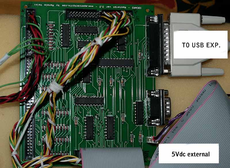
This card division mediates signals INPUT and OUTPUT. It is powered from an external source 5Vdc. Most of all I witnessed, powering the card from a source that is on the computer to which the card is connected. With external power supply I had a small problem.
- Top left, connected wires to the connector are flat INPUTS. Buttons, switches and encoders.
- Above are used OUTPUTS, such as LEDs, light bulbs, etc.
- Connector right, communication is either 25pin cable directly to the PC, but there is a need of this type of port on the computer. It already has most of the modern PC. Therefore it solves by purchasing the USB-EXPANSION card. So I solved it myself. It's simpler. Just be careful that the card was still connecting to the same USB and would not change its port number. It is entered in the config.
USB-EXPANSION looks like this:
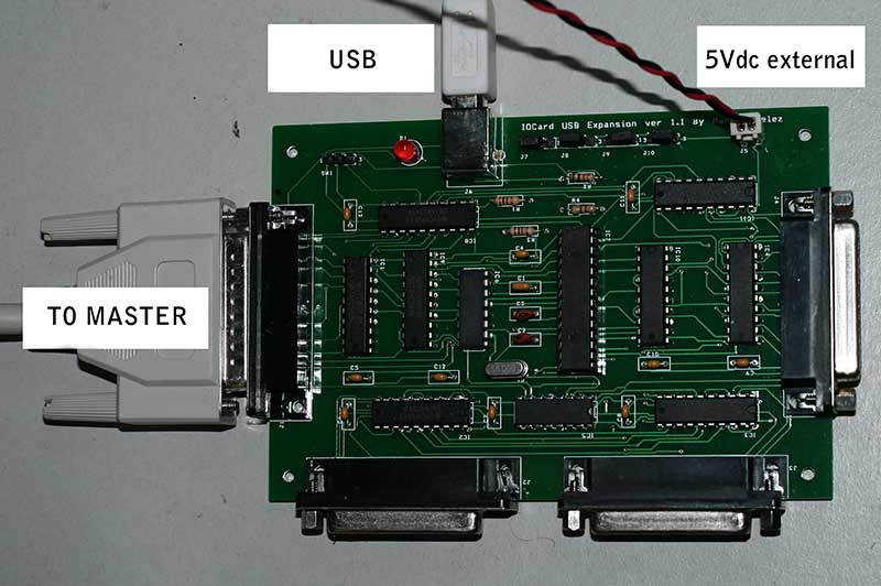
Connector cable is left to MASTERCARD, above the USB connector, which is in fact the main communication interface to PC. The card is fed back "booster" voltage 5Vdc. LED next to the USB connector blinks every time you press a button or switch is changed. USB card can be connected to each other four MASTERCARD.
Display numbers on the LED segments mediates called DISPLAYCARD-II (variant I is the oldest and less perfect).
DISPLAYCARD - II:
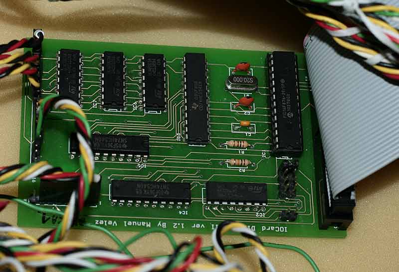
Ribbon cable on the right, this card is connected to MASTERCARD and one cable goes two of these cards. The connectors on the right side of each number are powered LED segments.
back to tne main.. back to the simulator