MCP .. Mode Control Panel
back to main menu .. back to simulator
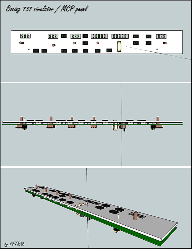
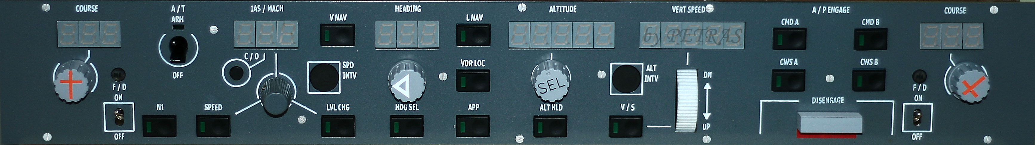
The MCP is so called because it contains controls that allow the crew of the aircraft to select which parts of the aircraft's flight are to be controlled automatically. In this precision piece of autopilot you can drive : Airspeed , Altitude , Heading, Vertical speed , Course etc. The first picture shows the initial proposal of Autopilot MCP panel, created using a simple 3D Google SketchUp. It's simple, intuitive tool for fully sufficient for rendering the basic concepts of the proposed configurations of components and units.
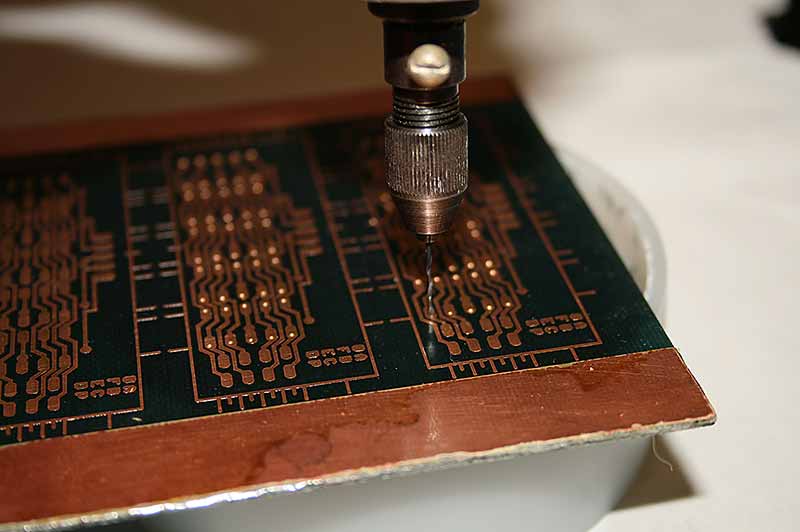
The next picture is drilling printed circuit board, which serves to connect the LED segments. These "dials" panel displays information on the autopilot and inform him about that course, speed, HDG, altitude and climb / descent as a digital numbers.
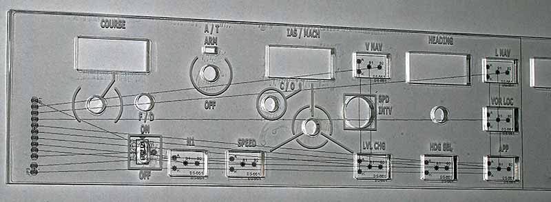
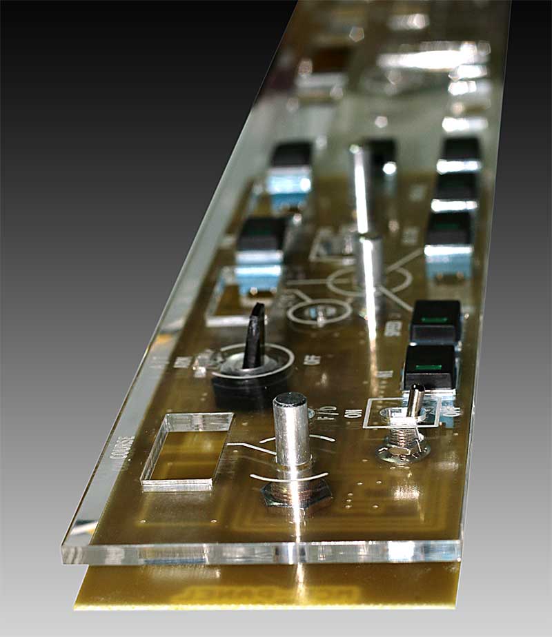
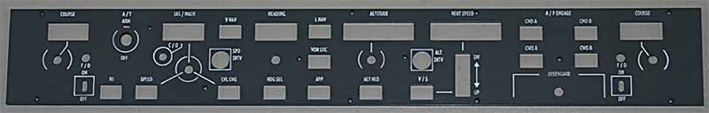
In this picture you can see plexiglass mask the MCP panel, laser carved and placed on a future drawing board. Simply check the correctness of the design of PCB and its alignment with the completed panel ...
12.3.2012 ...
The PDB I drilled only with small hand driller. All holes fit for the first time...( Clear Plastic is drilled with LASER ).
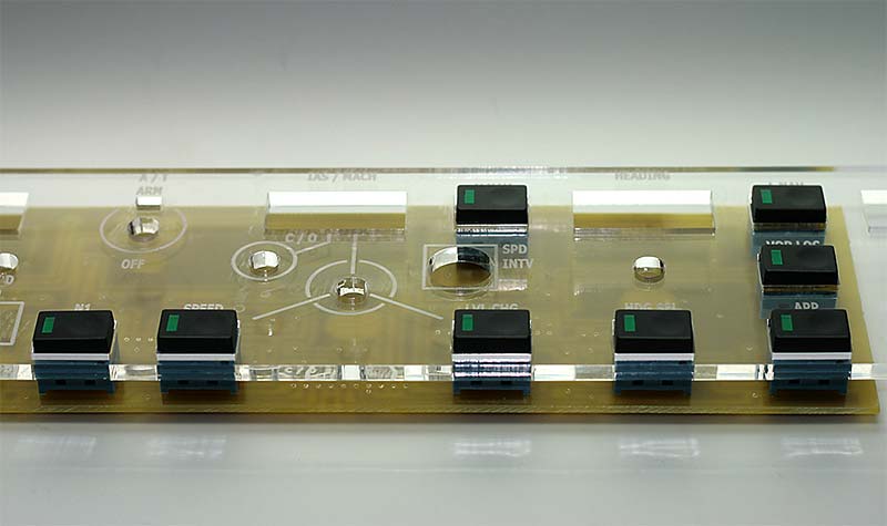
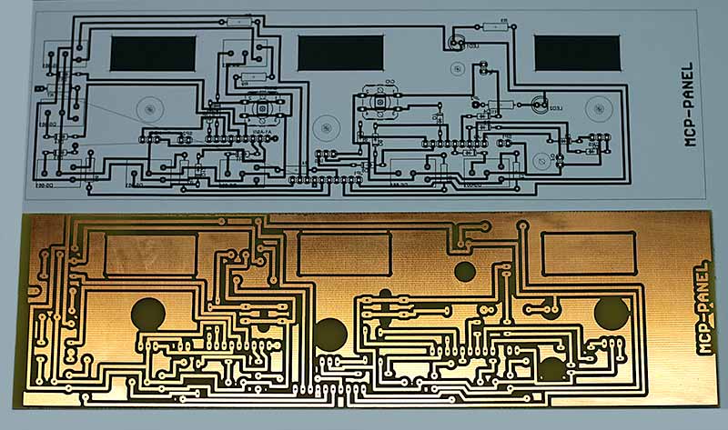
2012.04.09 ... after a long break (due to lack of time and workload) will again get to supplement my ongoing components of the simulator. I went back panel of the MCP. Already have produced both PCB panel. Because of the size, ie length, I divided the panel into two halves. Both PCBs have been manufactured, drilled and getting them planted. I will put here a few photos for illustration.
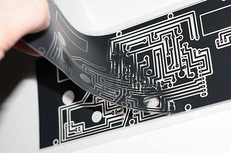
Here is a template made for exposure covering the second part of the PCB, which covers the active copper..
Fully staffed training without pcb soldering, testing only alignment laser "drill" holes. Panel "sat" on the first insertion. It is thus clear that the drawing was edited and produced on a laser mašince are unmatched precision. I can not imagine how I would square holes honed by hand. They're still unpopulated display.
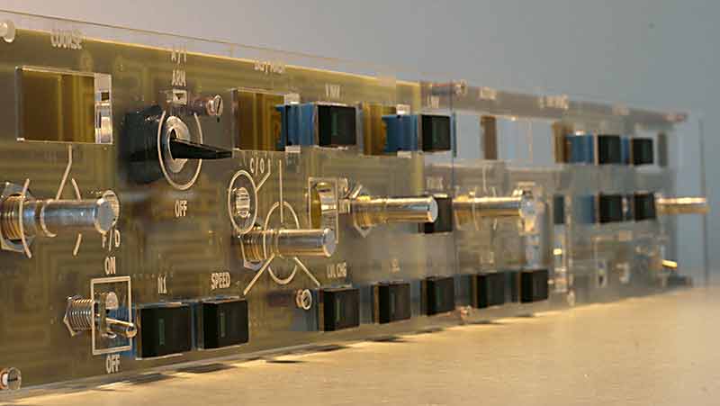
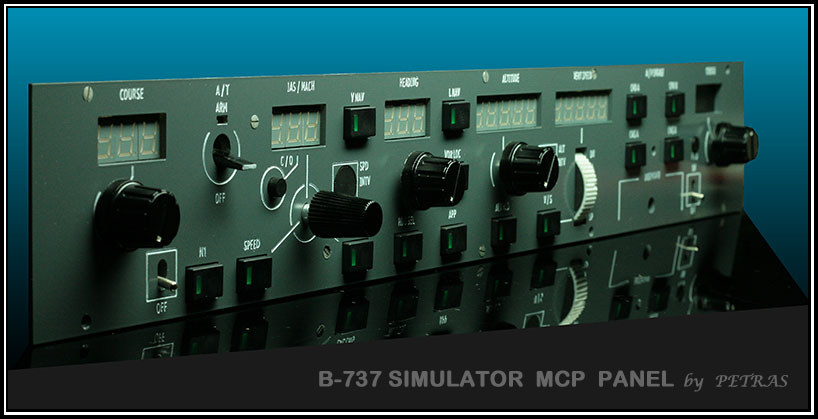
As a continuation of the MCP panel insert an image that is already filled with color and sprayed.
Now I expect to mount the encoder resolution, which controls the value of "VERTICAL SPEED". Is not the only driver with a rotatable shaft, but is in a vertical sliding window if (window with the arrow symbols and DN and UP).
2012.09.25
My last work on MCP panel for my sim you can see below
Panel is ready for testing with my software and hardware.
How it is nice you can se on the next picture. Panel is under power, connected to the simulator and driven with Opencockpit SIOC program.
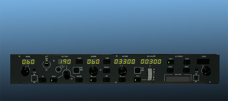
Only last button I must finish ... Autopilot off.
2012.10.14
Final version of my MCP panel :
( If you click on this panel, you can see bigger picture ).
Connection between MASTERCARD , two DISPLAYCARD-II you can see on the picture below.
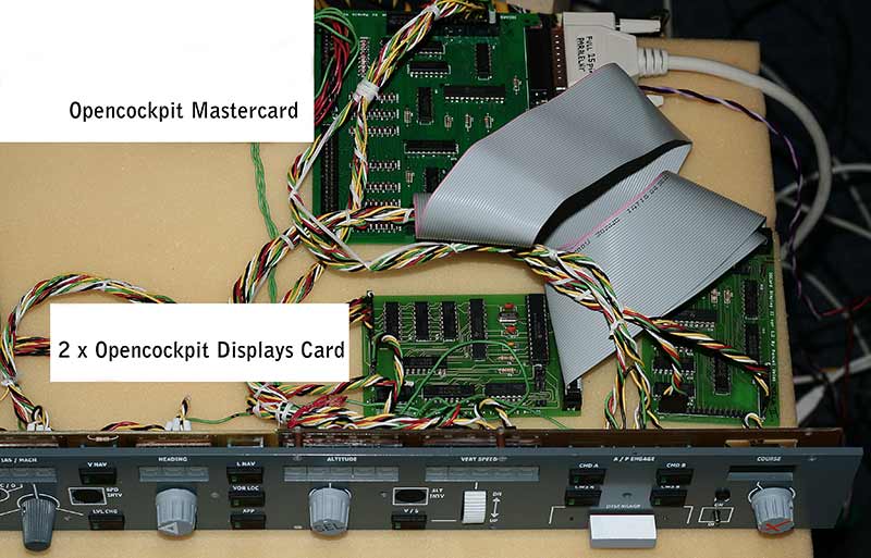
I use different connection then original Opencockpits have. I use A1 to A9 combination and 1 to 8 pins. Diods I have directly soldered on the PCB for MCP panel. I have less wires in that system.
back to main menu .. back to simulator