section 5).
FMS / CDU
back to main .. back to simulator
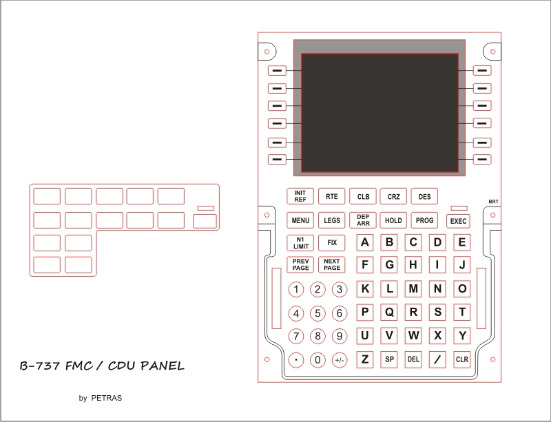
I start with drawing CDU panel chart for laser graver machine. I got a new 5,6" TFT LCD displays from Hong Kong.
First step of my work are in the pictures below. As a model I use Prosim CDU software and many pictures from net.
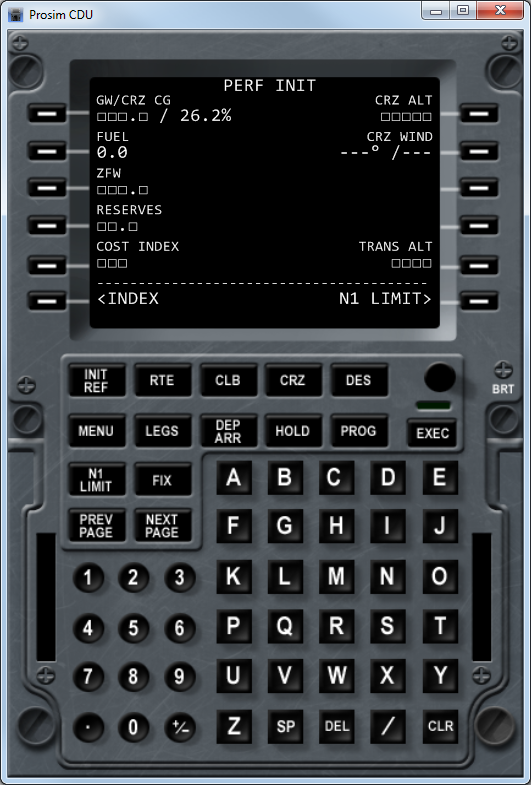
Gray rectangle indicates the actual position of the TFT display.
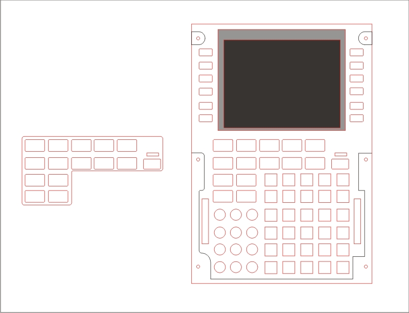
Red line in the picture will be laser cut to through. Then black line was only engraving with that machine.
From Opencockpit.com I ordered new " USB_Keyboard " emulator cards. They use up to 88 push buttons. It is fit to my project B-737 / FMS panel.
Some profi companies and some sim builders FMC / CDU panel's work with display the console from Sony. This principle, however, I do not like even a little bit. When I looked at the prices of external screens from this firm, the price of my solution is much cheaper and in addition, I think that even a technically perfect.
See for yourself how such a product then it looks. Display them on a round DPS, what in itself does not give much space to any design. Protrudes above outline FMS own ', so when mounting panel must " slip down under " outline the hole first and then attach.
I know what I'm talking about, because I took a few steps involved in the maintenance panel made and it was awful! Green PCB on the panel was glued weld hot gun, this connection lost and fell to the bottom of the simulator and stopped showing FMS work. ( The picture above is attached with screws and nuts ).
Also, it is easy to see from the picture, video cable, which is connected to this type of display to the graphics card. Card it must be equipped.
I would like to use square TFT displays avoided because it is equipped with both inputs, VGA and composite video Jack ...
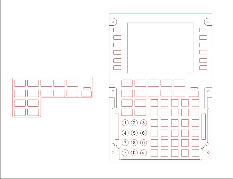
Last drawing, I hope that last one ( final version ) for my laser docu material.
Big printed circuite board for all buttons and LED are waiting for me now ...
12.12.12 ... ( 2012.12.12 )
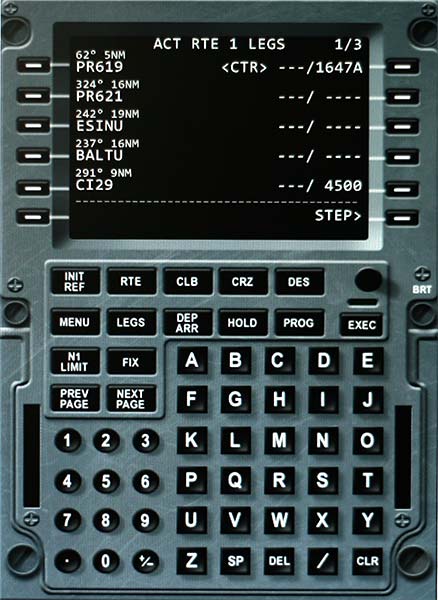
According to my wife's famous date in the calendar of some cultures. For me famous date in culture simulator fools. Today I had "lowered the water" in order Secondly, the longer dimension of the corresponding TFT displays ... Now 5 ". Displays I bought again from the Hong Kong firm transportation ais I had about ten days after ordering. works perfectly. For clarity, I made a few images from the simulator and test.
The first picture printscreen panel with FMC programmed tracks LKPR - Prague Ruzyne to LKKV - Karlovy Vary. It's quite illustrative only, nothing else, I programmed the onboard computer ...
The next picture shows the track as she sees left-pilot on the right screen your dashboard. The track is represented by a purple line, waypoints are then displayed as a four-pointed star.
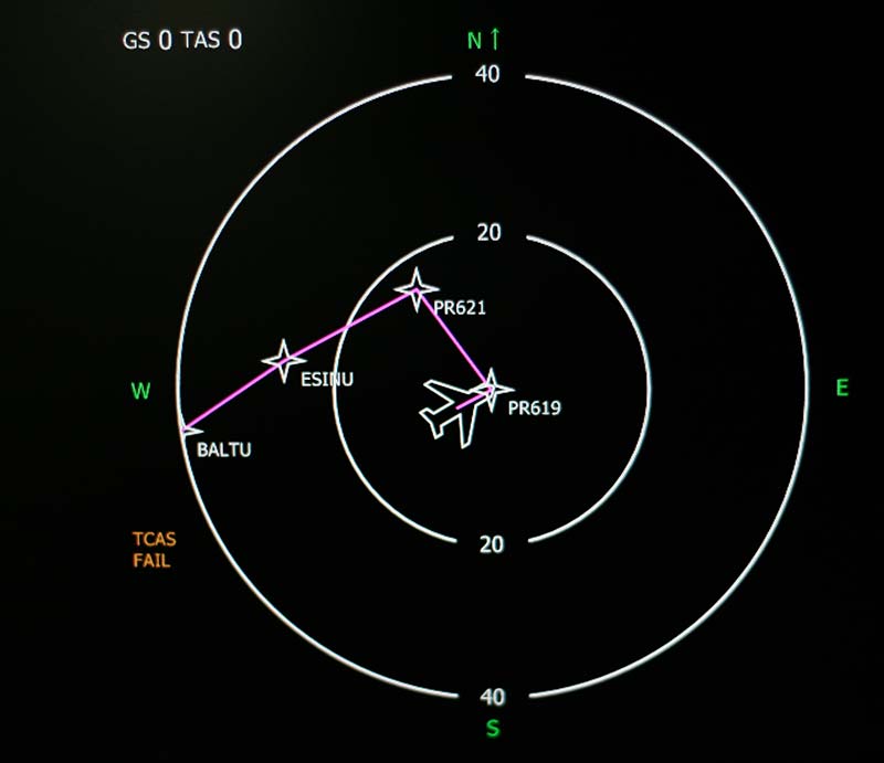
Well, so the track is displayed on the new screens, which can then be installed in FMC panel keypad.
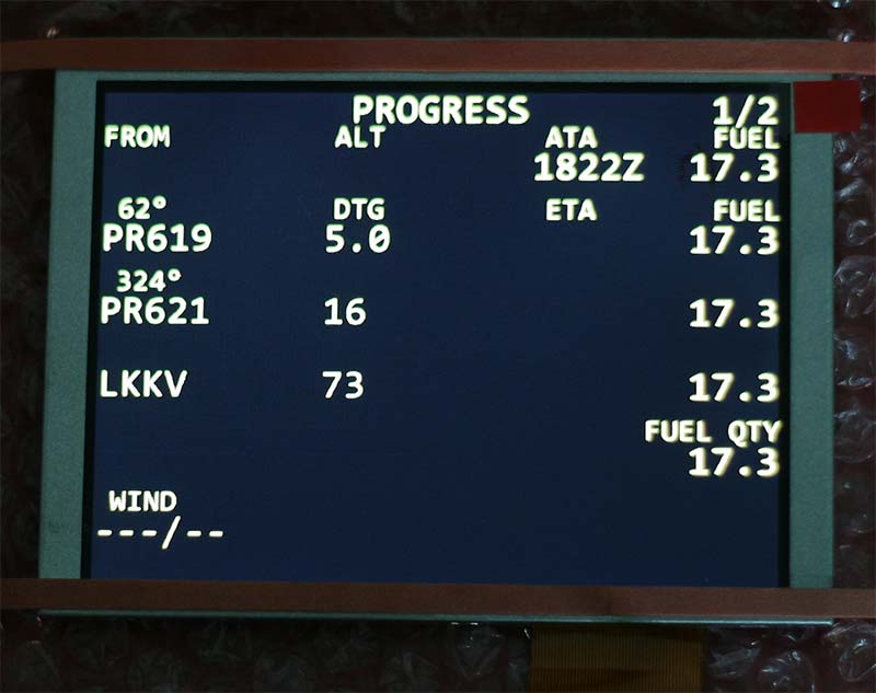
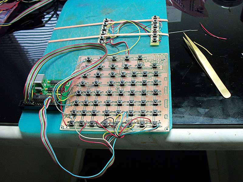
The entire assembly is PCB, electronics and control buttons displays are shown below. It's just a test board, I apologize for improvisation and rubber bands :-)))
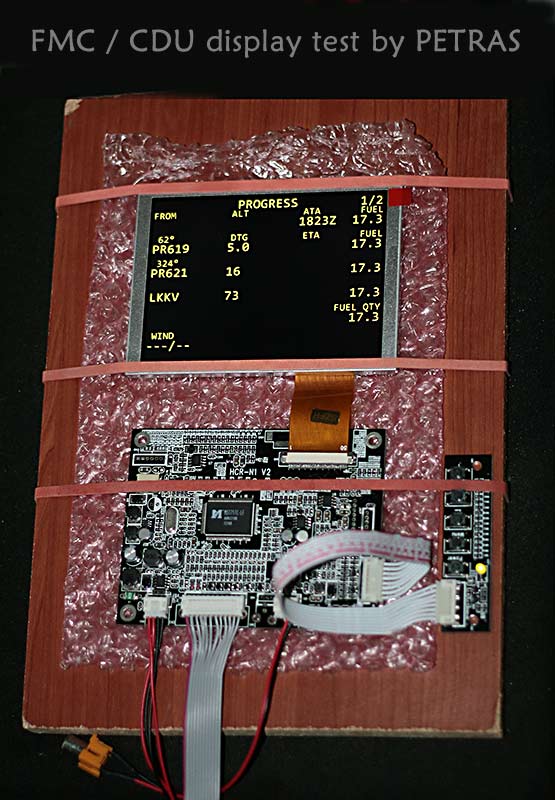
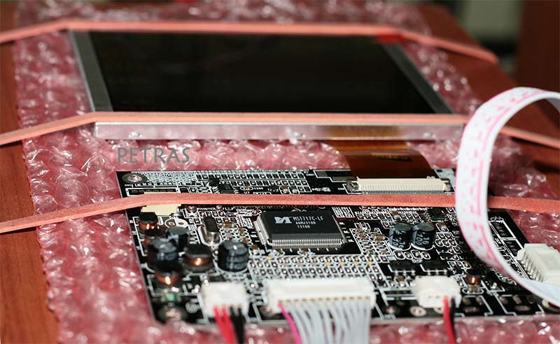
The last picture is a bit more detailed look at the board electronics.
Now I`m waiting every day for the postman with a new package from Opencockpits where I have arrive USB_KEY cards for manufacture of keyboards that will control this two FMC / CDU.
2012.12.20
Since networking on single-sided PCB (due to the simplicity of domestic production) nothing much about me some time takes. Probably inevitable few jumpers. The whole field "roads" I wanted to seduce into one jack and one would do it across a cable link with a printed circuit board USB_KEY. The resulting FMS will have 12V power connector for TFT LCD display, USB connector for connection to a PC and it will be all. Do I have to think ahead if you do backlights with LEDs, or if you do to simplify exposure controllable, but from outside. We'll see ...
2012.12.27 FMS/CDU
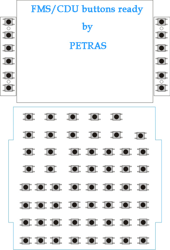
I worked on surfaces again and created a design printed circuit boards. Large, square is for the lower overall thin panel and two side buttons are beside the LCD screen.
Individual PCB are interconnected with wires. Big PCB will be connected to USB_KEY card through connector to disconnect the card went. It does not have the unsoldered.
On each side pcb has 6 buttons in total 12th. On the big board has a total of 57 buttons. This adds up to one FMS 69 micro buttons.
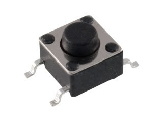
Control, which rests on the button, the laser slit part of the proposed panels with letters or characters. The price of these buttons is around 3Kč ( a few cents ). It's not so much. If there but you need around 150 pieces and more, so I multiplied it :-)) ... ( around 22 USD ).
2013.01.13
We have a new year 2013 and a lot of work around me. First picture with real PCB and new buttons.
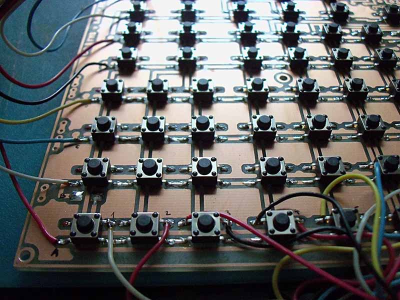
The next picture below shows the involvement of PCB with buttons along the lateral panels 2 x 6 buttons. On the left is also seen USB_KEY card connected 18 wires with plate buttons, the second link is only the USB cable to the PC.
Since the work is still a lot I need to engage our hidden reserves. The next picture is our son Dan, who now attended another lesson from training amateur electricians. LEDs stepped in and tried it, what is a "polarity". Successfully! Perhaps one successfully stands up for me ...

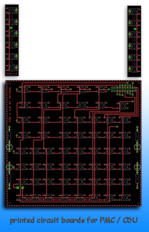
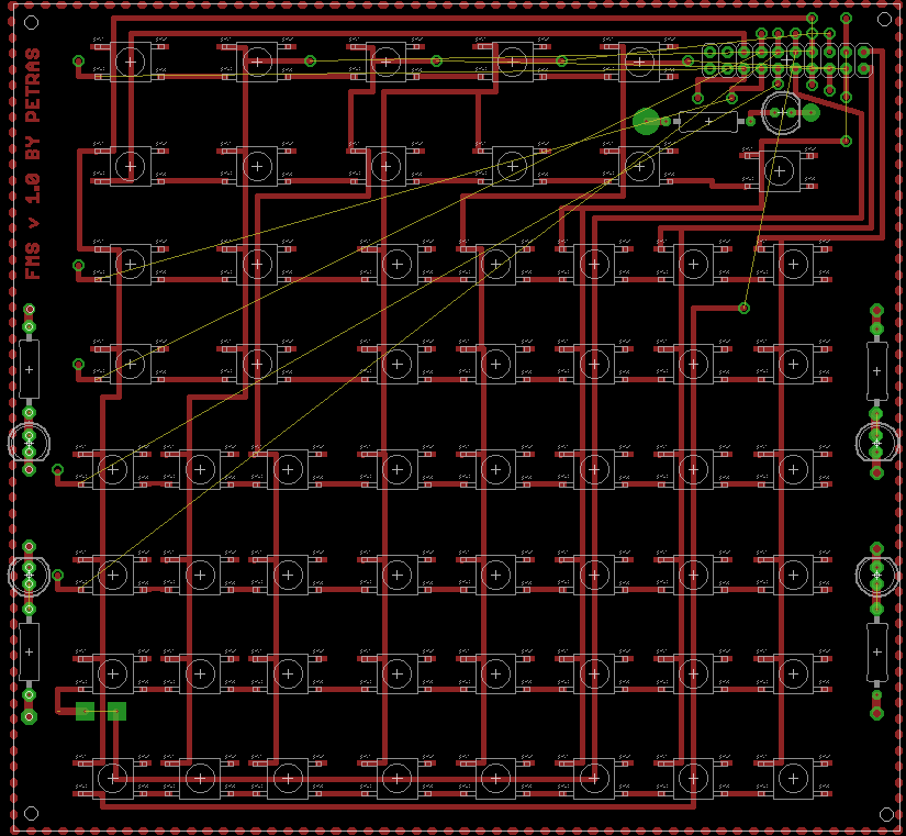
In today's last picture printed circuit board FMS v.1.0 by which I made a real PCB.
2013.01.15 PCB test with buttons and USB_KEY card...
I must premise right from the beginning that I was in fact pretty sweat. At home here I save fix PCB. Since the position of the wiring did not match the required buttons and numbers, I had to modify the wiring DPS. Unfortunately, I already had it done, so I had to scramble and bypass wires.
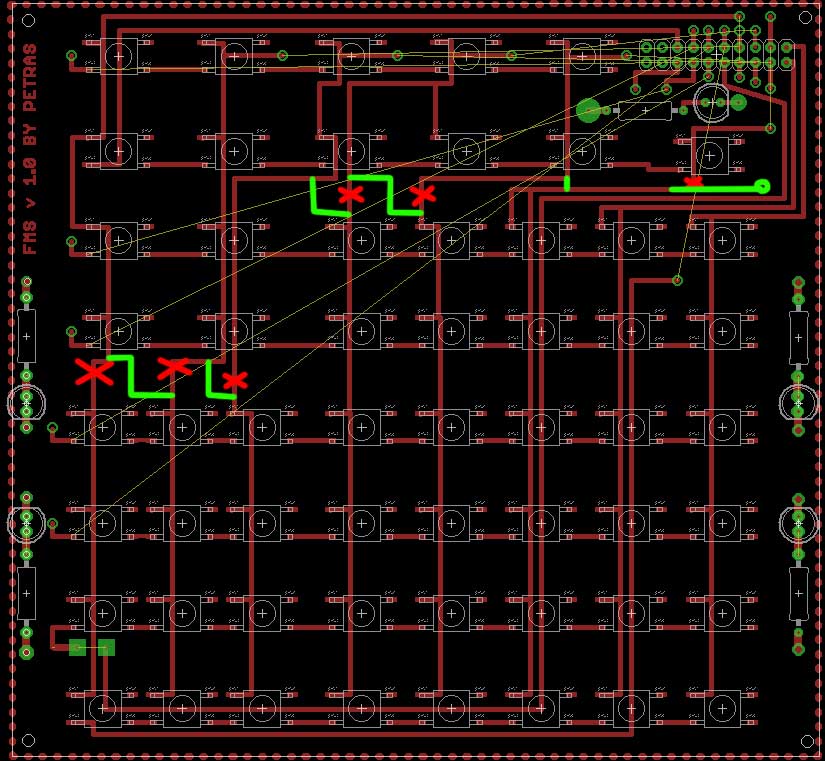
The figure also disagree with the fact those yellow strings that indicate connection wires and connector.
Repair and accurate table of the connectors and connector USB_KEY here I save my CDU later.
2013.01.17
So today, I reworked the schematic and PCB boards for an updated version v1.2. I adjusted the interconnection of individual sections of the connector that connects the PCB with connector card USB_KEY.
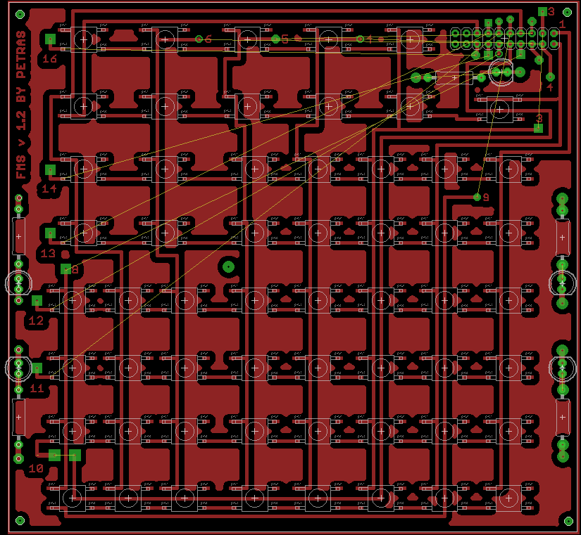
One section of the work which I called "blue" goes to pins 1, 2, 3, 4, 5, 6, 8 and a PCB line is vertical.
The second section is "red" and is connected to the pins: 9, 10, 11, 12, 13, 14, 15 and 16 The DPS is a horizontal line.
Attention:
- The first four vertical buttons on the left are connected to pin # 8
- Five vertical lines of eight buttons go to pins No.7,6,5,4 and 3
- One line after another seven buttons goes to pin # 2 ... together with circular letter keys are added and square button EXEC.
- Last vertical line of six buttons goes to pin # 1.
The picture below is a black and white variant of the PCB version 1.2
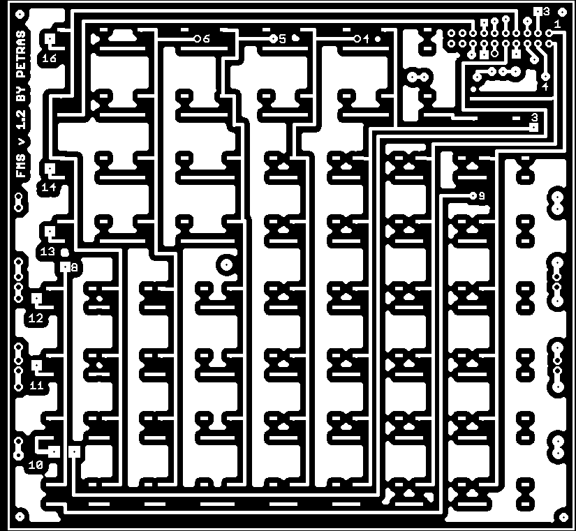
For connection betwen PCB and USB_KEY card I used two-row comb Solder plate drilled to about twenty pins.
2013.01.20 ... or enchanted weekend.
So I finally finished all the wiring FMC / CDU panel and connecting for connector between FMC and USB_KEY card. What surprises me, however, was waiting when I complete all interconnected and connected to the USB-LPs. Well, a few things I expected it, but the involvement and work of two-thirds. Side buttons figured a different code than I needed, some buttons dont worked well. Just somewhere I made a mistakes. Again, I checked all the colors, pins, links ... and the result? So I get involved, I have a stab at a PC simulator Cessna and I calmed down a bit over Switzerland. In the evening on Saturday, I was again plunged into wire-hell. I found that the side buttons are used to me incomprehensible combination of keys / buttons. Before I figured it out, it took me about three hours and fell to naught countless cells that fight even after previous brain left. But eventually, after several switching and scraped PCB work succeeded. On Sunday morning, the entire panel already working well. Glory!
To be in this for a few days, until I be plucking some wire from the joint, and I hade not black memory again, I've worked all connectors diagram. Maybe this will be the starting point for any builder who would like to model for my build something similar. Perhaps it will save someone hell that I experienced myself.
WARNING: It is a connection between FMC buttons, transition connector USB_KEY card, using SiOC software and software from the FMC-CDU Prosim737.
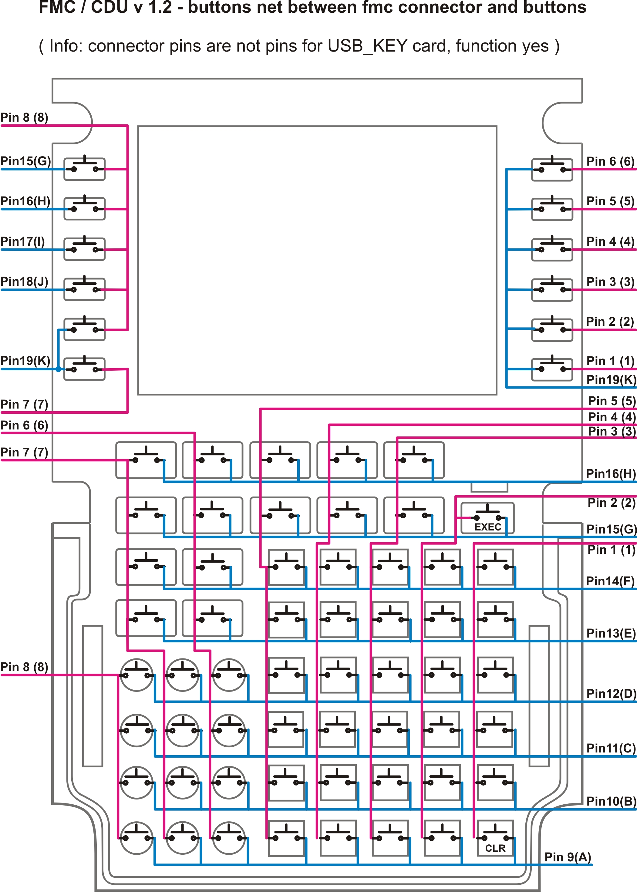
Wiring diagram buttons and connector, which is on the PCB FMC / CDU:
Next schematic for FMC and USB_KEY card wiring :

CAUTION: Not to be confused pin numbers with numbers and letters Columns and Row, indicating the position in the network. (This is also what the encoding of these).
As an example, I will be the No.1
- It has a position in the network COL = 1, ROW = A
- The image above is that the CLR key to efemesce.
- Connected but the pins and connector pin1 pin9.
So that large out!
back to main.. back to simulator