chapter 1).
ATTITUDE INDICATORS
back to main .. back to school
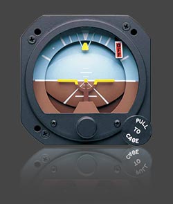
Attitude Indicator is one of basics gyroscopics aircraft instruments.
An attitude indicator, also known as a gyro horizon or artificial horizon, is an instrument used in an aircraft to inform the pilot of the orientation of the aircraft relative to earth.
Hi indicates Pitch and Roll and is a primary instrument for flight in instrument meteorological conditions.
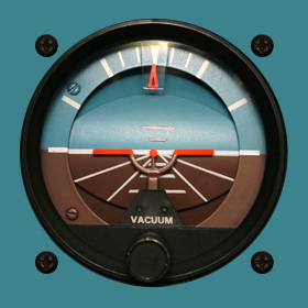
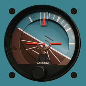
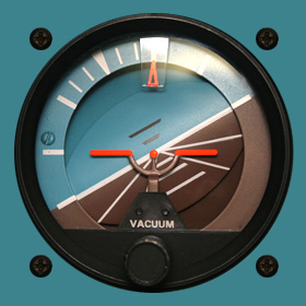
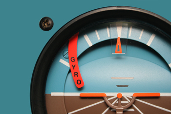
If the symbolic aircraft dot is above the horizon line (blue background) the aircraft is nose up.
If the symbolic aircraft dot is below the horizon line (brown background) the aircraft is nose down.
When the dot and wings are on the horizon line, the aircraft is in level flight.
Because it is the horizon that moves up and down and turns,
while the symbolic aircraft is fixed relative to the rest of the instrument panel,
trainees get confused; a standard corrective given by flight instructors is ,,Fly the little airplane, not the horizon.,,
All gyroscopic instruments should be mark on the cover with this label, which calls for special care

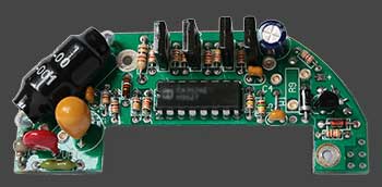
Electric inverter is on the picture above.
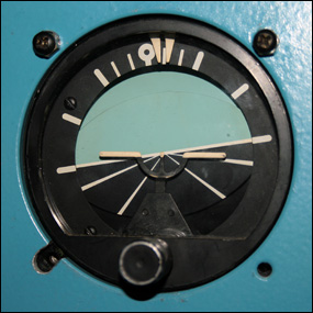
Now we can see how attitude indicators indicates.
Pictures from left to the right.. Airplane is without tilt , roll 10° to left and last one is roll 10° to right.
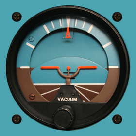
Pictures from left to the right.. Airplane climb 10° up, airplane dive 10° down.
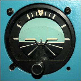
How we can see on the pictures, airplane symbol does not move. Inner part of instruments rotating towards frame of instrument.
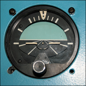
(put 2014)...for more illustrative symbolism I put on the page more pictures of another type of instrument.
Pictures from left to the right.. Airplane is without tilt 0°, roll 30° to left and last one is roll 30° to right.
Again pictures from left to the right.. Airplane climb 30° up and airplane dive 30° down.
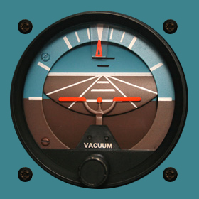
Next two pictures show you "Instruments warning flag" . That flag indicates that some types of devices is insufficient vacuum in the horizon.
When Instruments are with electric power, then flag pops up in the pilot's view, when the supply voltage is low, or low speed rotor gyroscope.
Left image ... everything works as it should. Right image ... bad vacuum in the rotor circuit, or the vacuum is turned off.

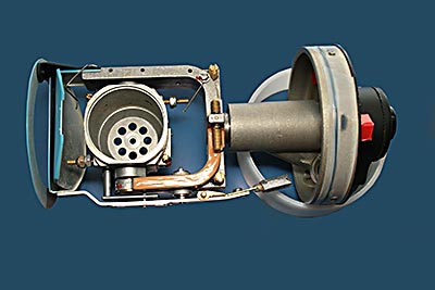
Frames and parts from Vacuum driven Attitude Indicator you can see on the picture below :
For example I have here an animation for lighting bezel ( if he have it ) :
Vacuum Attitude Indicator RCA22-7 on scorsby table test :
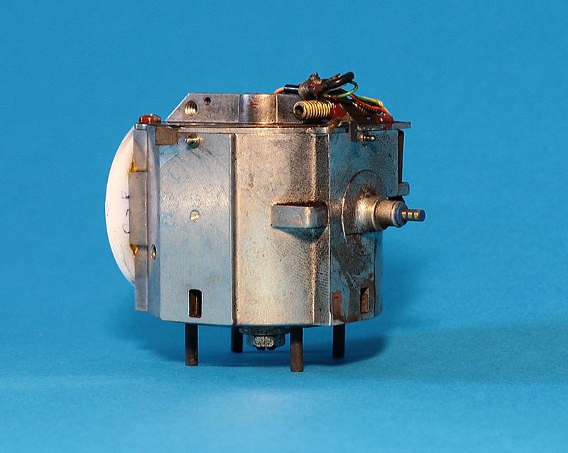
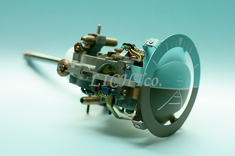
For you to have done a better idea what it looks like another type of artificial horizon inside the unit, I shot a couple of pictures while removing the artificial horizon RC Allen ... RCA26AKRC-2. It is an American artificial horizon for 14V DC power supply.
The first picture shows the internal frame, in which the means of two ball bearings on the sides of stored "housing" to the gyro rotor.
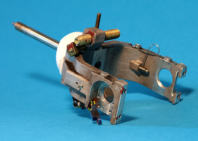
Rotor housing is shown below. This package holds its own rotor artificial horizon. The rotor shaft passes through this house. The underside is fastened with threaded counter-nut, on top of a slide is then stored in the canopy. Working position of the device is as shown.
It is evident that the axis of rotation of all artificial horizons is vertical! The difference in the directional compass, having a horizontal axis of rotation horizontal.
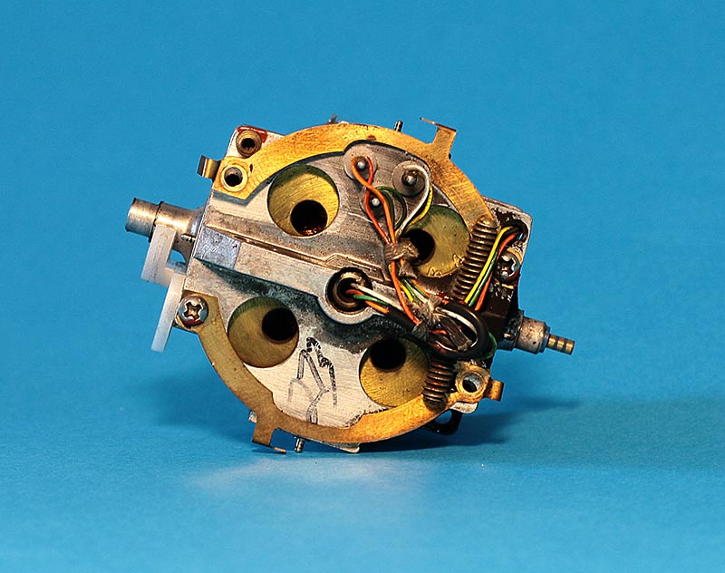
The next picture shows the assembly (Inner housing assembly) from above. Nice to see there are three phases of feeding the rotor (in fact stator) flywheel with color ORANGE - GREEN - WHITE. According to these colors at first glance can tell it's a drive / rotor / unit for power supply 14VDC. Plastic semi-circle on the left is a segment, which provides a mechanical lock artificial horizon imaginary "0", to the horizon. How large are the forces on the rotor spin you can imagine. If you do not advise I help you , to ... ... GREAT.
Therefore, I encourage all pilots with a strong arm, "Lock the artificial horizons gently, smoothly, and let the rotor time to roll over to the home position to the horizon."
It may happen that when you yell for locking all his strength, the plastic part breaks off, the stem is bent and will meet an unpleasant issue ... (figuratively in dollars) as new parts must be sent across the ocean. And it is expensive.
On both patterns are well visible collector for sliding contacts (original Slip Ring), which is used for rotor voltage. It is actually a rotary mechanism. It's blue - gold tube with three stripes.
Cooling holes on the upper side of the rotor can see a small piece of the stator winding.
The picture below is already set internal rotor deposed house with cross frame, supported by two miniature bearings. Again there is a beautiful to see stronger shaft that stands right, and is finished off with collector again. With it, the voltage transferred to the outer frame and then to the drive.
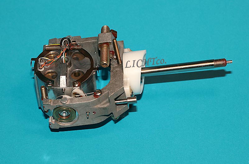
Each device / instruments have two sets of Slip Rings and the path is as follows:
- On-board aircraft 14VDC network
- Switch for Power of artificial horizon ( I recommend to insert protection element / circuit breaker-fuse )
- Leading to the connector housing / rear side
- The changer / inverter is inside the unit which already comes from the AC voltage on the three phases
- First three contacts of Slip Ring (on the back of the outer frame)
- Wires
- A second trio of Slip Rings (on the side of the inner frame)
- Keeping the stator of gyroscope.
On the bottom left picture is still nice to see unconnected collector of brushes. Six wires pantograph is there because each phase uses two wires for the voltage increase transmission security.
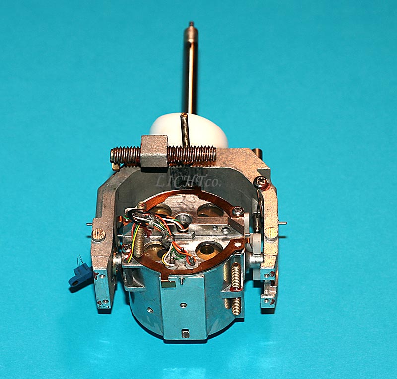
In that picture you can see completly assembled inner frame for RCA26-AK2 horizon.
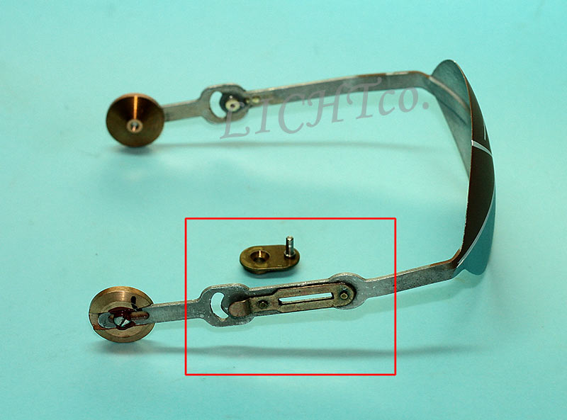
Next picture and red frame around show you small stainless steel pin and a backdrop for transmitting of gyroscope motion.
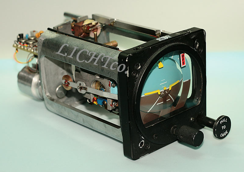
The last picture of the series RC Allen Horizon 26AK-2 is the entire assembly, but without the outer metalic cover. In the top right of the device is nice to see a warning flag indicator, which indicates the poor condition of the power. Usually indicates the absence of voltage from power supply, the lack of advanced diagnostic gyroscope rotor speed.
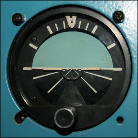
To illustrate how various concepts appear displaying information about the position of the airplane,are at the following two pictures. This is an older Russian-made and this is reflected symbolism. The first picture is the type AGK-47, AC power 3x36V / 400Hz, which is used e.g. in hellicopter Mi-2. In this position, the device is balanced color black in all fields and the pilot is governed only by the position of "planes" toward the central bar. If the aircraft climbs, the symbol goes over the line, if declining, logically goes down. It is the same tilt. Planes in the right heel is tilted to the right, the left, on the contrary left. It is mechanically adapted to the gear which movement on slopes gyroscope is rotated 180 degrees. Brown and blue color is displayed in the longitudinal inclination to values exceeding 40 degrees. In angle inclinations color is not presented.
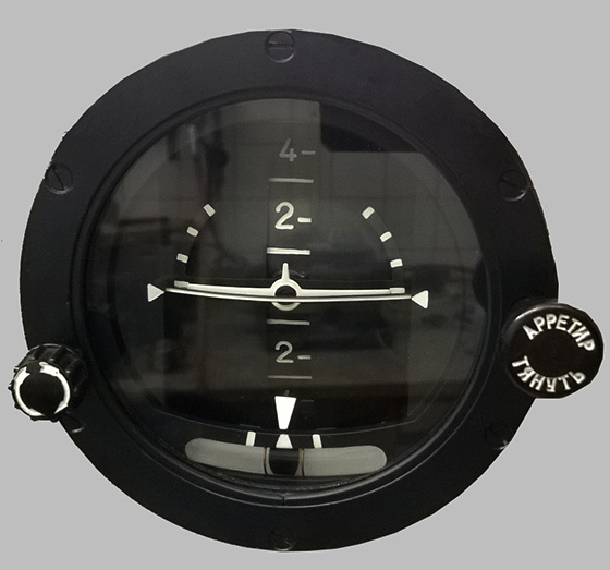
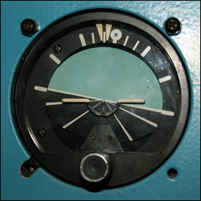
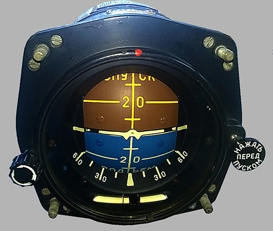
The second figure is then very old instrument called AGI-1 (avia Gorizont istrebitelja). The symbolism is the same, like Czech made Attitude Indicator LUN-1202, which was used in many of our motor sports aircraft of that time. I understand technically, why is brown on top, but I would according to him, therefore he did not want to fly. I think contemporary instruments with a blue on the top and brown bottom are somehow better. This device is fully aerobatic, but I don`t like brown on the top! The power supply voltage is used again 3x36V / 400Hz. The last time I met him in the Jak / C-11th trainer.
The next picture which I made is a picture for an idea of how looked an artificial horizon bearings. The larger, for larger loads are obviously bearing outer (lateral) frame, the smaller are for house, which holds the rotor (the hair creates a longitudinal frame) and thus indicates the longitudinal slope equipment or aircraft.
All bearings, which are essentially using are from the U.S. producer. The company NHBB prescribed by the Manual for the Overhaul of instruments. (Original ... New Hampshire Ball Bearings)
The first two letters in the title mean SSRI is Steinless Stell.

Informations for the Bearings I will not write more. I have plan for the future, to write a separate chapter.
They are integral and I`m not afraid to say, the main component of which depends on the reliability and accuracy of the functioning of all gyroscopic instruments.
back to main .. back to school